Fragmentation in Networks
Fragmentation is the process of breaking down packets in network communication into smaller pieces so they can traverse a link with a smaller Maximum Transmission Unit (MTU) than the original packet size. These fragments are reassembled at the receiving end to form a single packet.
A packet typically cannot be larger than the maximum permissible size of the network when sent. The Maximum Transmission Unit (MTU), which is usually consistent, determines this size. Generally, the MTU size of modern office or data center Ethernet-based networks is 1500 bytes. If the packet size exceeds the network’s MTU, the data within the packet must be fragmented. This process divides the packet into smaller units (fragments) that are equal to or smaller than the lowest MTU in the network.
Network Fragmentation Process
RFC 791: RFC 791 specifies the algorithm for fragmentation, transmission, and reassembly of packets in a network.
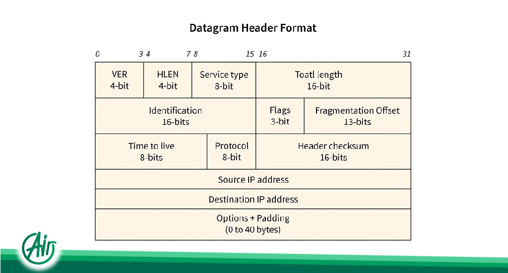
RFC 815: This RFC defines an efficient reassembly algorithm. The Identification field in this algorithm’s packet header, along with external and internal internet addresses and protocol identifiers, and the Fragment offset field are used for fragmentation and reassembly in the IP header. The Don’t Fragment and More Fragments fields are used to manage the fragmentation and reassembly process.
If a receiving host receives a fragmented packet, it must reassemble the packet and send it to the higher protocol layer. Although reassembly is intended to occur at the receiving host, in practice, it might be performed by an intermediate router. For instance, in NAT (Network Address Translation), an intermediate router may need to reassemble fragments to translate data streams.
Fields in the IP Header Fragment
- Identification Field – 16 bit As the name suggests, this field is used to identify fragments of a frame.
- Offset Field – 13 bit This field determines the sequence of fragments in the frame. The maximum possible value for this field is (65535 – 20) = 65515 (where 65535 is the maximum datagram size, and 20 is the minimum IP header size). Therefore, we need ceil(log2 65515) = 16 bits for the fragment offset. However, the fragment offset field only has 13 bits. Thus, for efficient representation, the fragment offset field must be reduced by 216/213 = 8 as a scaling factor. Consequently, all fragments except the last must have data in multiples of 8, so that the fragment number belongs to N (multiples).
- More Fragment (MF) Field This field indicates whether more fragments follow this fragment, i.e., if MF = 1, more fragments follow, and if MF = 0, it is the last fragment.
- Don’t Fragment (DF) Field When fragmentation of a packet is not desired in the network, this field is set to 1, and the packet is transmitted as a whole.

Why is Fragmentation Necessary?
Datagrams generated by the network layer in the source system traverse multiple networks before reaching the destination system. Typically, the source computer supports the transmission of large datagrams. This is because if a datagram is divided into smaller fragments, the header for each datagram unit is repeated. The header is repeated for each fragmented datagram, wasting the source network’s bandwidth. However, each network has a ceiling on the MTU. Worse, the source system is unaware of the packet’s route to the destination. Therefore, the source cannot determine the size of each fragmented datagram.
Reasons for Fragmenting a Large Datagram into a Fragmented Datagram:
- Data capacity is limited by the hardware and operating system used in the network.
- Compliance with national and international norms.
- The packet size can be adjusted according to the protocols of different networks.
- Larger packets occupy the network longer than smaller packets.
- Reduces errors due to retransmission.
What is a Datagram?
A datagram is the smallest unit of data transfer in a communication system. Datagrams are data packets that contain enough header information to independently route to their destination through all intermediate network switching devices. The network layer receives data from the upper layer and encapsulates it with a header. Thus, each datagram includes data and a header containing information about the data and services.
Fragmentation of a Datagram
Each LAN or WAN has a limit on the MTU size of sent packets. If the datagram exceeds this size limit, it is fragmented and created at the network layer. Only the data within the datagram is fragmented. The datagram header is repeated for each fragmented datagram to ensure that the information in the header remains intact even after fragmentation. The datagram is fragmented both at the source computer and at each router along its path to the destination. The network layer delivers the fragmented datagram to the data link layer. Subsequently, the data is encapsulated in frames and directed to the router.
The protocol used in the physical network from where the frame is created determines the format and size of the received frame at each router. To send the datagram to the next router, the router unpacks the datagram from the received frame, processes it, and then re-encapsulates it. The size of the sent frame determines its movement to the next router or system. When the data link layer encapsulates it in a frame, the datagram’s overall size must be less than the MTU. If the receiver has a smaller MTU, even a fragmented datagram may be further fragmented in the routers to match the receiver’s MTU. Also, only the data inside the datagram is fragmented, and all datagram fragments copy the necessary part of the header.